In this series of articles, I present the overall design of my LED cube. I try to emphasize the key points I had to take into consideration and the decisions that I had to make before settling with the final version that in turn will be assembled in reality.
Since I have no prior experience with similar projects, so I based my design on these instructions that are pretty thorough and cover almost every details. However, I needed to slightly change the design at some point. I recommend studying that article, because I will only highlight the differences. Some parts were not available and I tried to keep the costs and part number at minimum to have a clean design. But don’t rush too far ahead, let’s start at the beginning.
Main parts
According to my plans, my working LED cube will consist of three distinctive parts. The first one is the cube itself without any electronics that I’m going to discuss in the next two sections. The second part in the driver electronics that is responsible to supply appropriate currents and voltages to show up the desired image on the cube. The third part is the controller which is the programmable “brain” of the cube. Its main part is a microcontroller IC that controls what image or animation to play on the cube.
Cube layout
I employ the same layout as in the original design. My cube consists of 8 layers, each layer contains 64 LEDs in 8 rows and 8 columns. All LEDs in a layer are connected together by their anode leads. The layers are stacked on each other and the LEDs directly above each other are connected together by their cathode leads forming 64 columns. This is called common-anode configuration and it differs from the original design where the cathodes were connected in a layer (common-cathode). The cause of this change will be discussed later. To light up a specific LED, we have to connect the ground to the selected column’s terminal and some positive voltage to the selected layer’s terminal. This layout results in altogether 72 terminals: 64 for the columns and 8 for the layers.
As shown in this video, at a given time only one layer is active by selecting some of the columns, then the next layer is turned on with possibly different columns selected, and so on. This is called multiplexing, and if we switch layers fast enough, the human eye can be fooled to see all layers active at the same time resulting in a 3-dimensional image. This effect is called persistence of vision or POV for short and utilized in almost every display device from LED panels to televisions.
LEDs
Since only one layer is active at a time, each LED is lit only 1/8 of the time (which gives us 1 / 8 = 0.125 = 12.5 % duty cycle). This also means that the visible brightness of the LEDs are 1/8 of their maximum brightness. Standard LEDs have brightness around 40 mcd (millicandela, thousandth of the brightness of a candle), way too dim to use in the cube. That’s why I was looking for ultra bright LEDs that start from 1000 mcd and above.
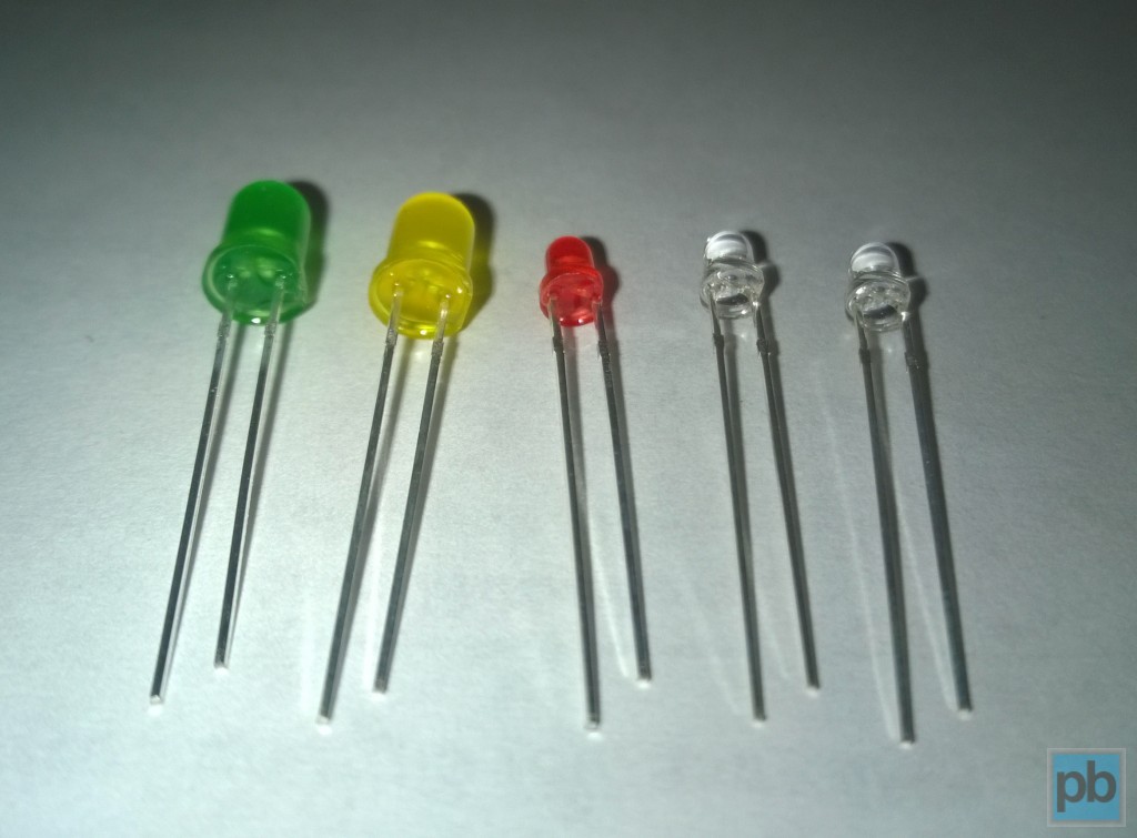
These are LEDs in various sizes and colors. The two on the left are 5 mm diameter, the others are 3 mm. The ones to the right have clear housing while the other three are diffused ones with colored housing. You can see the two leads: the long one is the anode (positive), the short one is the cathode (negative) terminal. The cathode is also marked with a flat edge on the LED casing.
However, ultra bright LEDs are slightly more expensive and since the cube contains altogether 512 LEDs (8×8×8), this little price difference begins to matter. So I looked around on Ebay, by ordering directly from China I could save up to 70% compared to buying from local suppliers here in Hungary. The original design recommended diffused LEDs for better 3D light distribution, but unfortunately diffused LEDs with this brightness levels are quite rare to find at a reasonable price. So I ended up ordering 5000mcd clear LEDs in orange colour. Almost every cubes around the internet use clear LEDs, so I guess they will be alright.
Driver circuit
The driver circuit does nothing else but selecting exactly one layer and – at the same time – selecting the appropriate columns (0-64) to light up in that layer. Besides that there are two main reasons why we need dedicated driver electronics:
- According to the layout, there are 64 column wires and 8 layer wires to control which LEDs are lit. No microcontroller has this many I/O lines, so the driver circuit employs some kind of multiplexing electronics that maps the 72 cube terminals to much fewer I/O lines.
- Depending on the actual 3D image shown a layer may have all its 64 LEDs turned on at the same time, which needs quite a lot of power. Microcontrollers contain fine circuitry that can’t handle high currents, so we need some electronics between the cube and the controller that is designed to deal with such high currents.
In the upcoming article I will discuss the driver circuit in more details.
Dear Mr. Peter Budai
I’m a retired electronics & instrumentation engineer involved in academics & industry during my employment years. Now I do some microcontroller (PIC18f4550) electronics especially moving display using 8 x 8 matrix displays since that is complete I have set my sights on making a cube matrix display starting with a 3 x 3 x 3 cube. I know its working but while looking for more on the subject I chanced on your massive project. Thank you for the theory and the accompanying video. Good job and regards.